COMPANY DETAILS
• FillRite Technologies
✆ (866) FILLRITE
✆ (866) 345-5748
• info@fillritetech.com
 Problem
As infrastructures age, the demand for expensive repairs increase. Failures can cause contamination, lead to sinkholes or roadway damage. Sliplining is a common upgrade for an aging septic infrastructure. Common for septic pipes, a new carrier pipe is installed within the original host pipe. Flow is transitioned into the new carrier pipe abandoning the old host pipe. Between the two pipes is a void space. This annular space is still susceptible to water filtration,
cave-ins, and root growth. Left untreated, this space can pose as a risk to the new carrier pipe or the supported roadway above. Filling and sealing the annular space is an important step to extending the life of the newly revived infrastructure and surroundings.
Fall of 2022, an installer contacted the Engineering Support Program at FillRite Technologies to discuss the benefits of using a light weight foam to fill this annular space. Their client was evaluating the use of CDF (Controlled Density Fill). Unfortunately CDF was heavy and would not seal and protect the exterior of the new carrier pipe. Additionally, delivery of the product in the congested work zone would be difficult. Lightweight FillFoam could be installed quickly from port to port offering a complete void fill.
SUMMARY
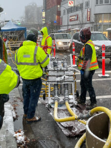
Located in Western Canada, this annular space encompassed nearly one mile of sliplined septic pipe that required void filling. The void space was between the nearly 5 ft diameter host pipe and the newly installed carrier pipe that measured just over 4 ft in diameter. The sections to be filled varied in distance from 200-400 feet long, commonly from manhole to manhole. Each section required a pumping point and a vent point. Traffic control was utilized to close down one lane with minimal disruption to traffic. Accommodation were made to continue operations despite the cold winter temperatures and snow. Containment areas with a hydro-vac extracted any waste water displaced from the pipe during foam installation.
Various densities of FillFoam were installed into the annular space and pushed forward or backfilled. High density foam was used to travel further distances while lower density foams could be used for shorter
distances or smaller voids. Throughout the project samples were retained to verify density and yields.
CONCLUSION
Over multiple mobilizations, the contractor installed nearly 300,000 pounds of FillFoam material into the annular space. Materials were shipped via totes in concentrate within 8 truckloads. A volume of over 1,000 cubic yards of FillFoam foam was produced onsite at a rate of nearly 30 cubic yards per hour. Had the contractor decided to install
CDF, over 100 truckloads of material weighing over 40,000 pounds each would have been required. For months trucks would have needed to navigate the congested downtown area further disrupting traffic and causing additional strain on the road.
Problem
In Fall of 2019, FillRite Technologies was contacted by an HMI installer regarding a project opportunity. They had recently heard about FillFoam and saw an opportunity to utilize the product on an upcoming city project. The city was in the planning stages to remove the aged waterlines running down the center of the main state road. With the water main centrally located on the road it would require full lane closures and detours for any repairs or maintenance. Originally, city engineers planned to excavate 6,650 feet of the road to remove the old 6” water pipe. They would then install the new water main along the shoulder and re-pave the road. The contractor began to educate the city on FillFoam and how this product could be used as an alternative to demolition. FillFoam could be installed inside the water main and laterals to abandon the pipeline in-place and avoid excavation.
FillFoam is a pre-expanded polymer foam pumped with hydraulic pressure. When pumped from a positive connection, pressure can be maintained to push material from one point to another. The liquid foam will cure and solidify within hours and harden into foam. Variable densities with a range of compressive strengths and resilience modules can be pumped based on the project needs.
Extensive research was completed to compare repair options. The preliminary option to excavate and remove the old pipe was expensive, time consuming, and labor intensive. An alternative was proposed to abandon the water main and laterals in place by filling the pipes with FillFoam. The new water main would be installed along the shoulder to avoid detours and traffic control. This approach would limit demolition to every 650 feet. Abandoning the pipes in place and installing new pipes would be faster, less invasive, create less waste, and require less labor and heavy equipment.
Solution
The project was postponed due to the COVID-19 pandemic and resurfaced again in Spring of 2021. The contractor worked extensively with the city and prime contractor to plan out the logistics of the project. Due to State regulations, it was required that the construction site be limited to 3 blocks under construction at a time, instead of access to the full 6,650 ft of pipe and laterals. This would limit access to 10 different sections. Each section would need to be completed prior to moving onto the next section. Each pipe section would be up to 650 feet long with laterals. Some pipe sections would be blocked at one end and others could be filled from beginning to end.
Work began the Summer of 2022. Vented sections of pipe where foam could be pumped from beginning to end had two fittings installed. At the pumping end a 2” pipe was set with a combination of polyurethane foam and hydraulic cement plug. It was crucial during polyurethane foam installation that the end of the installation pipe was not clogged. Soil was then backfilled and compacted and a custom fitting was installed at the top of the injection pipe. It is important that the plug be strong enough to resist the back pressure created by pushing material forward.
A vent test was performed to confirm the pipe section was clear. Compressed air was pumped into the pipe and monitored at the vent end. This test identified when an inline vent was closed or there was a blockage. If air was unable to pass from point A to point B, foam would not pass.
Summary
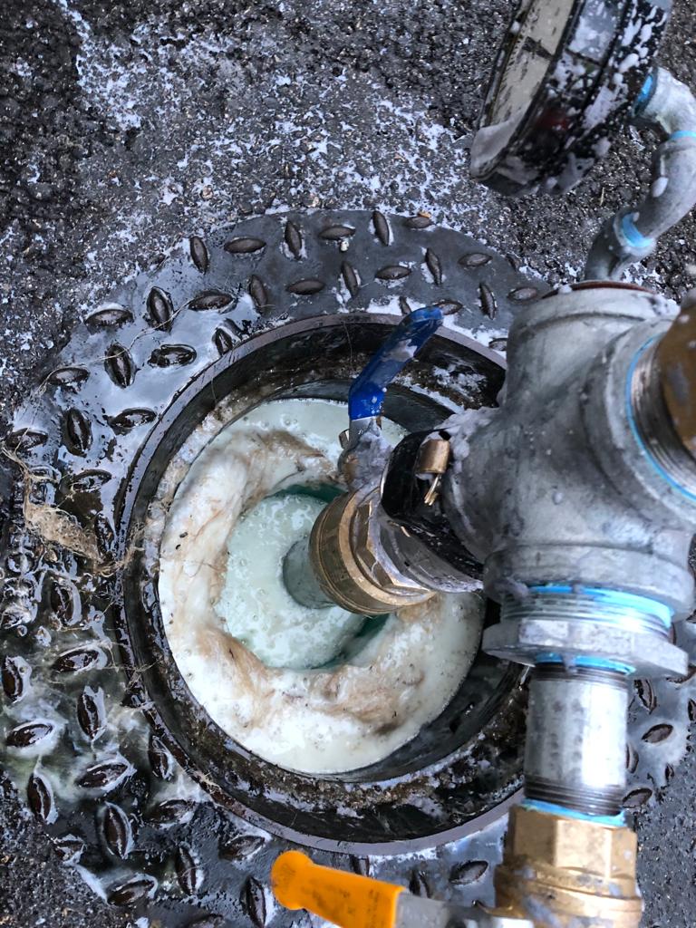
FillFoam material was pumped until foam exited the vent end. As foam moved through the pipe, water and debris was pushed out the vent. Through the 6” pipe foam traveled at a rate of approximately 40 feet per minute. Pipe sections and laterals filled ranged from 350 to over 650 feet.
Laterals off of the main pipeline were treated as vents and fitted with a valve. As foam was pumped and began to exit the lateral vent the valve was closed. This regained pressure and allowed the foam to continue traveling forward toward the next vent. Each vent was closed until foam was discharged from all openings, signifying a complete void fill.
Non-vented sections of pipe were filled by installing a 1 inch diameter hose into the section. Because air could not vent out the opposite end, the annular space around the injection pipe acted as the vent. FillFoam was pumped through the injection pipe to the end, foam then continued to flow backwards around the injection pipe until foam came out around the injection end of the pipe. The pumping hose was also abandoned in place.
The next day after work was completed, injection and vent pipes were cut and plugged with hydraulic cement. Road crews could immediately work to install the new water main and re-pave the roadway. Work is schedule to be completed by Summer of 2023 as crews finish one section at a time.
PROBLEM
Milwaukee, Wisconsin- A park pavilion regularly used for youth programming and other activities was awarded a donation for an expansion to be made on the 1970’s building. During the construction of the addition, the area was backfilled with ¾ crushed stone to prepare for concrete to be poured. A spread footing was built and the framing was constructed for the future wall. Unfortunately, the fill was improperly compacted and could not support the weight of the footing. The project engineers and contractor were concerned that the gravel would also settle under the weight of the slab after it was poured. So they contacted their local concrete lifting and stabilization contractor.
SOLUTION
The concrete lifting contractor team designed a plan to stabilize the gravel and increase the load bearing capacity. This plan consisted of two parts. The first part was a layer of polyurethane foam to be installed to bind together the loose gravel. HMI HF 402 was chosen because of its unique foam characteristics.
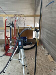
The second and final stabilization technique was to install FillFoam™ to fill in around the stone and lock into place. Precision laser measuring equipment was utilized to monitor for movement and identify when foam was installed until refusal. It was very evident when installing pipes at depth that the lower layers of gravel were not compacted. Various densities of FillFoam™ were installed throughout the project. Higher densities that were more fluid were installed where further flow was required. This allowed material to flow under the stairwell. In other areas, flow was limited by installing a lower density FillFoam™. With HMI/FillFoam’s engineering support, the local contractor was able to successfully stabilize the gravel for the building addition.
SUMMARY
1,800 lbs of HF 402 Fast were installed for the top layer. 2,119 lbs equivalent to 8 cubic yards of FillFoam™ were installed into the loose gravel. The next day, crews poured the slab over the top of the stabilized gravel.

Railway Culvert Fill- Canada
Problem:
FillFoam Canada was approached by a Canadian rail company to assist with the abandonment of old culverts running under their railways. Old culverts were made of corrugated steel which had begun to fail in certain locations under the tracks. The client wished to fill these culverts to reinforce the structure ensuring the ground above them would not fail in the future. They also needed to ensure that water was not able to flow through and continue to erode areas that were already failing. Once these culverts were filled, the ends would be crushed and buried into the railway embankment.
Client concerns included the following: Traditional methods were time consuming, expensive, and complicated. Traditional abandonment products were not eco friendly and posed challenges during installation. For example, concrete slurry mixtures would “blow out” during installation, requiring a major cleanup operation. They also require heavy equipment which when operating beside highways would require extra resources for traffic control and other safety measures.
Solution:
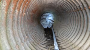
FillFoam Canada presented a solution to the client that would provide all the benefits with none of the risks or complications. FillFoam Canada built a 50 ft injection nozzle and capped the far end of the culvert leaving a single exhaust port. The 50 ft nozzle was placed into the 75 ft culvert creating an injection point 25 ft from the end. Foam was pumped in from this point until it pressurized the far end and began coming out of the port. The port was then plugged, and the nozzle was pulled roughly 10 ft back towards the open end of the culvert. Each time the foam moved 10-15 ft back towards the injection end of the culvert, the nozzle was pulled back as well. Keeping roughly 10 ft of foam between the open end (injection side) of the culvert and the end of the nozzle. This approach kept the foam under positive pressure during installation allowing it to fill to the volume of the culvert. Once the foam reached the injection
side of the culvert, the nozzle was slowly removed while the pumps were still running to ensure that any void left behind was filled.
Once removed the pumps were shut down, a process that took roughly 2 hours per culvert. FillFoam Canada’s approach removed the heavy equipment requirements as the only equipment required onsite was a ¾ ton truck
and trailer. This eliminated the need to shut down one lane of the highway and manage traffic as equipment was moved or operated. This approach also eliminated concerns related to spills. The cleanup of concrete slurry is a much more involved process as the product is highly flowable and often a leak leads to many yards of liquid concrete spilling into potentially sensitive areas. Fillfoam cleanup is extremely fast, safe, and efficient.
SUMMARY:
FillFoam Canada put a plan together that successfully accomplished the client’s goal of filling and burying abandoned culverts. This plan was completed faster and at reduced cost and complexity when compared to the slurry alternatives.

Sturgeon Bay, Seawall Repair
Problem:
Records water levels in Lake Michigan led to voids behind this 100ft long seawall in Door County. High waters allowed water to wash up and over the sea wall daily. When this water drains back into the bay, it brings with it some of the soil under the slab. Without the support of this soil, the walkway settled. Because these levels could increase with high winds or additional precipitation, it was important to replace the eroded soils and support the concrete.
SOLUTION:
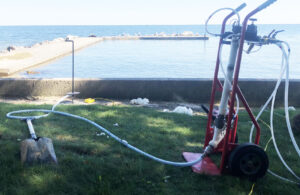
A series of holes approximately 5 feet apart were drilled into the walkway. FillFoam™ was pumped as a flowable foam into one hole until foam traveled up through the next hole. This process continued until the complete void was filled.
SUMMARY: This project was completed in 4 hours and required 900 lbs of FillFoam™ to fill the void that was up to 4 feet deep. This produced a volume of over 4 cubic yards of foam. This foam filled the void and displaced the water collected under the walkway. The foam will not change shape or wash away like the previous soils did. FillFoam™ can relieve soils of access water, but will not interrupt the natural drainage of water back into the lake. This lightweight
solution was also strong with over 20 PSI of strength. After the foam was cured, crews returned to install polyurethane foam to raise the walkway back to the original height. This project was completed with a standard capacity FillFoam™ unit installed in a trailer. 100 ft of hose was used to reach this area with limited accessibility.
WAREHOUSE VOID FILL

PROBLEM
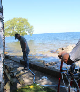
An interior floating slab had been compromised due to a fire riser break. The fire riser ruptured, and flooded out thousands of gallons of water under the slab, and created a large void. The Fillfoam contractor was contacted to evaluate the void.
SOLUTION:
The FillFoam installer was awarded the job due to the quick and effective void filling solution. First, a portion of the slab was cut out while another portion was deemed salvageable by the engineering firm by use of the Fillfoam installment. The installer strategically drilled holes into the slab to insure proper coverage of the Fillfoam installed. The fillfoam was pumped quickly and safely, with zero heat. Fillfoam is the ideal choice for any void. It flowed easily to the deep crevice created.


SUMMARY
This void was filled in just one day with 3,000 lbs of FillFoam. After the void was filled, a layer of polyurethane foam was installed on top before the concrete was poured above.

PROBLEM
A drink manufacturer facility was in the midst of building renovations when they realized there were many voids beneath the facility. Because this well known bottling plant was held to strict sanitary standards, the floor was washed daily and led to this void under a 20×30 ft area of 4-12 inches in depth. In order to save on expense and downtime for the factory, they awarded this job to the local void filling company to install to install FillFoam™ under the factory floor. This allowed them to keep the companies factory floor on its three shift schedule and they didn’t need to move the heavy equipment.
SOLUTION
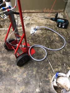
Test holes were drilled in various places to see the void in each area. FillFoam™ was safely installed through a 1 inch hose in a 20×30 area. Two different densities of FillFoam™ was installed to complete this void fill project. A total of 800 lbs of FillFoam™ was installed. The FillFoam™ installation took 2 days in comparison to a week it would have taken with shutting down the equipment, moving the equipment and removing the current concrete bring in backfill and repouring concrete. Once installed, the small holes were patched. There was no mess left as the excess FillFoam™ was easily washed down with water or picked up and disposed of that flowed outside of the building while filling the voided area.
Midwest Facility Void Fill
PROBLEM:
It was identified that there was a failure in the floor drainage of a food production facility. This slow drainage resulted in a major void and multiple pipe breaks. Because this facility was held to strict sanitation requirements, the equipment and floor was washed down regularly. Every time wash down occurred, water would drain into the compromised piping and more fill would wash away. What started with only drips of water and small particles washing away developed into a major problem.
The primary void was 60ft long and was a void size of 4’x4’feet at the worst area. The void ran perpendicular to the main forklift aisle. The worst part of the void was directly under the aisle. As soon as these voids were identified the entire factory was shut down. This factory shutdown cost the plant millions of dollars in downtime and loss of production.

SOLUTION
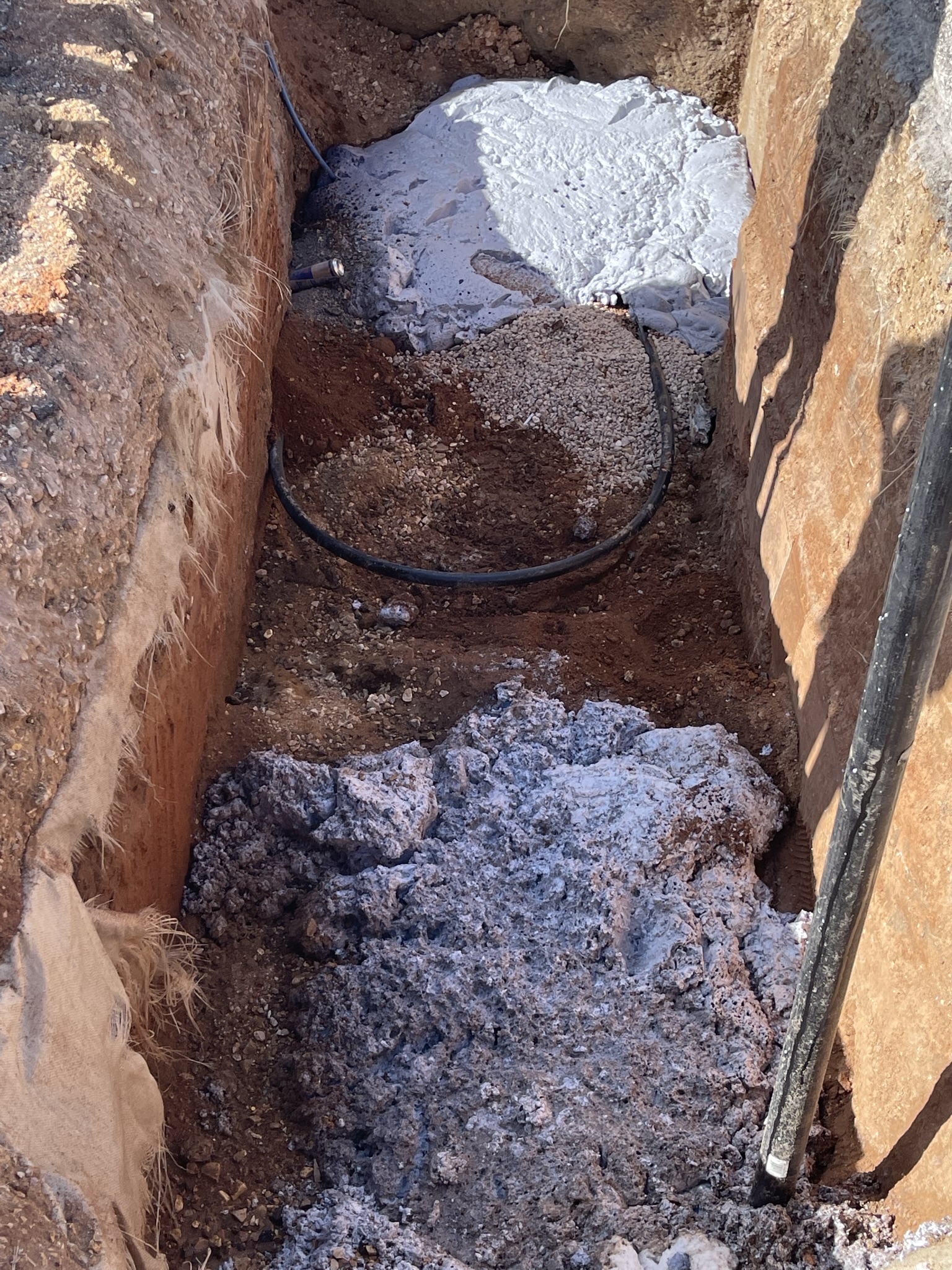
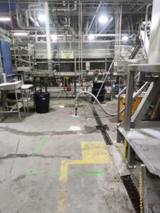
Prior to any repairs, the void needed to be filled to support the slab and construction equipment needed to install the new drainage system. Through two injection locations, 4,947 lbs of FillFoam material was installed, equaling a volume of 20 cubic yards. The complete void was pumped in 1 ½ hours. Within 24 hours a trench was dug through the cured foam to install new drainage pipes (picture below). Reinforced concrete was poured over the repair site and the plant was re-opened for operation.
SUMMARY
The speed of mobilization from the FillRite team and FillFoam installation helped the plant save significant money and avoid longer downtime.
PROBLEM
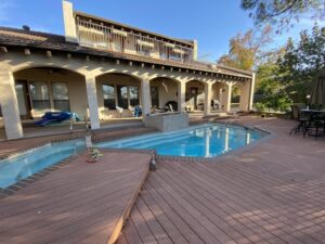
A 20 year old residential pool in Arlington, Texas had settled around the entire perimeter upwards of 5 inches from end to end. This caused the skimmer pump to start sucking air and for the waterline to be off. The pool was located on the side of a hill and the soils began to erode and shift, causing the “foundation” of the pool to shift. A common problem for structures built on hillsides.

SUMMARY
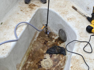
A local FillFoam installer was contracted to stabilize the pool. They first installed steel piers under the entirety of the pool to achieve the necessary lift. Next, they strategically drilled five 1-inch holes through the shell of the pool. They then installed 4 cubic yards of FillFoam to fill the void created during the lift. By using FillFoam, they were able to ensure that the void was completely filled using a minimal amount of holes. FillFoam is a two-part mixture of a resin and hardener and was chosen for this project because it does not lift and can flow hundreds of feet from the injection point. This process was important to stabilize the pool before further erosion could occur and to prevent costly repairs.
SOLUTION
This project was completed in just 1 day with 4 cubic yards of FillFoam. The contractor was able to save the homeowner the time consuming and costly repair of reconstructing the pool had it continued to settle.
PROBLEM
This Midwest church has had drainage challenges since construction. Water shedding off of the building would flow under the slab as it traveled to the drainage system. This created a channel for water to flow under the slab. Years of water flowing through this channel eroded the soils supporting the parking. Within the past 15 years the congregation elected to mudjack the void to support the slabs. Eventually the problem did arise again as the mudjacking grout eroded like the original soils, this time assisted by a leaking fire hydrant and sprinkler system. Seeking a more permanent solution, the congregation contacted a local contractor for other options.

SOLUTION
FillFoam™ was installed under the voided slab. The depth of voids ranged from 2-18”, additionally there were up to 4 feet of weak soils below the slabs. The majority of the holes used to inject FillFoam™ under the slab were from the previous installation of mudjacking material. This provided a 10 foot grid pattern. FillFoam™ was pumped under the slab until it started to come up through adjacent holes and along the joints between slabs. The holes were then plugged and more foam was installed. This allowed the foam to build pressure and flow further. It also helped compact the loose soils and fill the voids under the slabs. FillFoam™ will travel the path of least resistance. FillFoam™ will not travel out other cracks, joints or holes until enough foam has been installed to build pressure and push out past the slab.
SUMMARY
68 cubic yards of foam were installed under the parking lot to support the slab. This job was completed within 8 hours with the Hi-Volume FillFoam™ System. The Church can now be confident that the material supporting their parking lot
will not wash away or interfering with drainage.

Sturgeon Bay Boat Launch Void
Problem:
Located on the Bay of Lake Michigan, this boat launch has survived many seasonal changes. Seasonal trends provide high and low water levels, storm surges and ice shoves. From the surface, this appears to be a private boat launch. However what you see is not the original boat launch slab. Under this visible slab is the original slab that had settled significantly and a new ramp was poured over top. For many years, waves have crashed onto the shore line and drained back into Lake Michigan. With every wave more and more soil was eroded. As the shoreline began to fail, it was built up with additional rip rap. These large rocks created a stronger barrier against the waves and ice, but did not prevent water from shedding down and under the slabs. The homeowner watched year after year as more shoreline eroded under the slabs. They knew the slab needed to be supported so they contacted FillRite for a solution
SOLUTION:
FillFoam™ was installed under the boat launch slabs. This material was pumped as a flowable foam. Six holes were drilled through this thick three foot slab, around five feet apart. The crew started with filling the top of the boat launch and moved down towards the water. While pumping through the bottom drilled holes, air was escaping through the cracks at the bottom of the launch under water creating visible bubbles at the surface. While the FillFoam™ was pumped under the slab, the foam started flowing to the other drilled holes. This process continued until the voids under the slab were effectively filled.

SUMMARY:
616 lbs or 88cu ft of FillFoam™ was pumped under the boat launch. This void project was completed in 2 hours and
the boat launch was ready to use immediately. FillFoam™ is hydroinsensitive, water does not impact how the foam
cures into a solid foam. After FillFoam™ cures, it is inert and will not changes shape. Now as the waves crash onto
the shore, the water can drain naturally, uninterrupted by the foam supporting this boat launch. Unlike the soils
that settled or eroded, FillFoam™ will hold strong and will not wash away. The homeowners are thrilled with this
permanent solution that will now support their property and hold up to the harsh conditions Lake Michigan can
present.
Problem
A void filling/Deep Foamjection contractor was called by a homeowner who noticed some erosion behind the concrete seawall at his bay home. The property was located on a canal. Due to poor rainwater drainage around the home, tidal movement, among other variables, there was an extreme loss of soils around the property. This erosion had created a substantial void and cavity underneath portions of the home’s foundation and the entire 110 linear feet of sidewalk that connects to the seawall barrier cap.
Furthermore, after performing multiple soil tests along the seawall barrier, using a Dynamic Cone Penetrometer, the soil testing report indicated weak soils at the 6.5 ft depth which was calculated to be just below the water level at high tide. It was also noted that the location of the voids and unstable soils were consistent with the seams where the concrete panels were joined.
The homeowner had already explored other options to repair his failing seawall but was unsatisfied with the price. One of the alternatives was quoted to be well over $50,000 and a minimum of 3 weeks to complete. The alternative option would have required an extremely invasive process of ripping up the entire connecting sidewalk and excavating around the home and seawall. The homeowner decided to go with this installers non-invasive option which included a two stage process using HMI™ polymer resin technologies. Firstly, stabilizing the deeper subgrade soils followed by filling the large voids and cavities underneath the connecting sidewalk and home’s foundation.

SOLUTION
The installer completed the soil stabilization process using HMI’s Deep Foamjection™ method. The Deep Foamjection™ method consisted of injecting high density polyurethane foam to specified depths behind the seawall in order to reestablish the load-bearing capacity of the soils and sealing the concrete panels from future water intrusion. The material used for this stage of the project was HMI’s expansive polyurethane 402 HydroFoam due to its tremendous hydro-insensitive polymers and ability to set up in wet environments. For the soil stabilization stage, a total of 22 injection points were installed behind the seawall and approximately 55-70 lbs of foam was pumped per injection point at specified depths of 6.5 ft and 3.5 ft into the subgrade. The material density was 4.1 lbs/ft 3 and a total of 1,300 lbs of 402-HydroFoam material was installed along the seawall barrier.
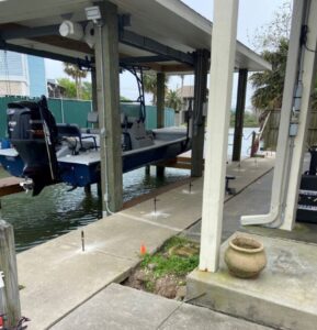
The second stage of the project, void filling, was completed using FillRite Technologies FillFoam™ material which is a pre-expanded flowable foam engineered for large void fills and soil stabilization applications. FillFoam™ is hydro insensitive, highly versatile, and is an excellent engineered material for soil repairs and improvements. For this stage, a total of 2,180 lbs of FillFoam™ material was installed at a density of 8 lbs/ft 3 in order to sufficiently fill the voids underneath the edge of the home’s foundation and underneath the 110 linear feet of connecting sidewalk.
SUMMARY
The two stage process of soil stabilization and void filling was completed in a total of 50 hours, roughly 5 full days of work. The customer was extremely pleased with the success of the project, saving him time and thousands of dollars; all while completing the operations with minimal invasiveness to the surrounding environment.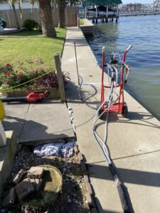
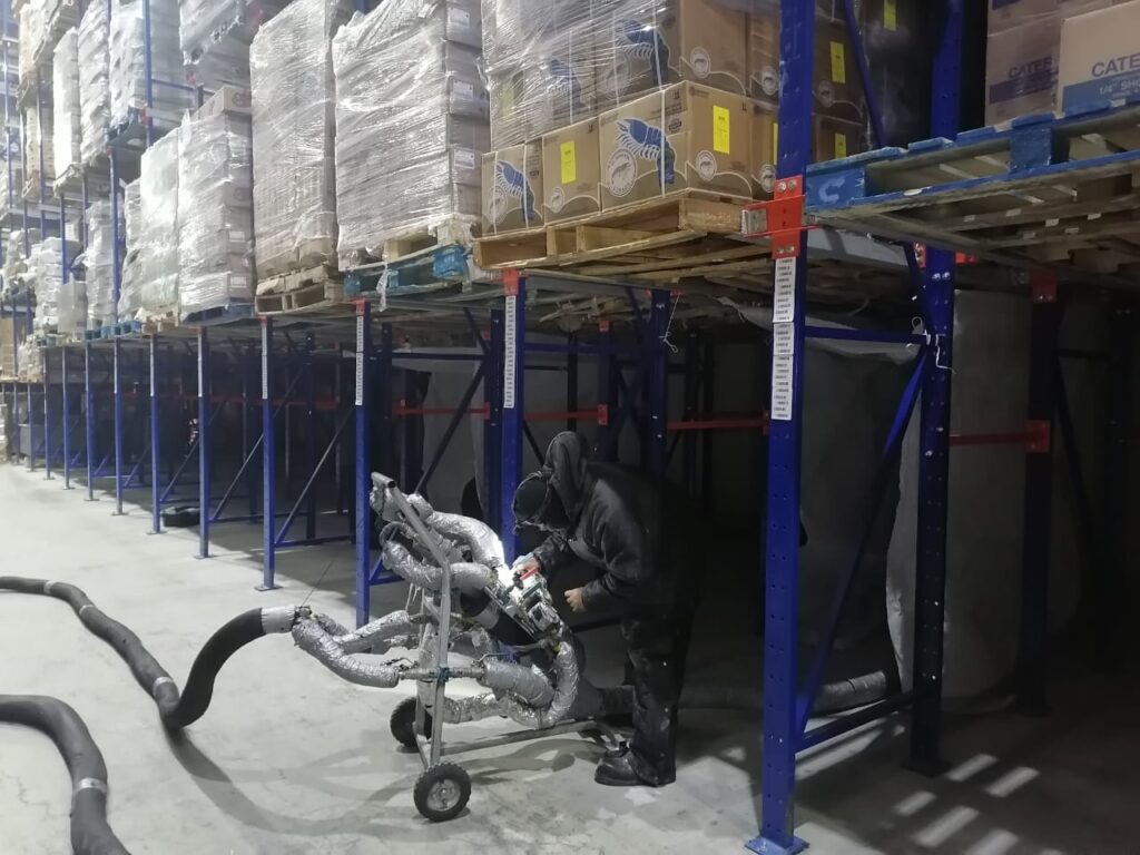
Two Acre Warehouse Freezer For Perishable Products
AT A GLANCE: The freezer was built between 2017 and 2018. It has an area of 2 acres and is used to store perishable foods at a temperature of -10°F to -25°F. The floor of the freezer was designed to resist sub-zero temperatures. The concrete used was type MR-48 of compensated contraction with a thickness of 12”, built in two pieces. Under the concrete slab, 6” of thermal insulation and pvc- based respirators were installed on top of the embankment and controlled gravel.
THE PROBLEM
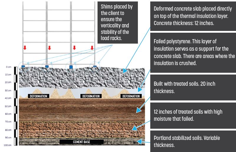
In 2019 the freezer began to present cracks in different areas. By the end of year 2020, the two concrete slabs that make up the freezer began to sink from the corners. This could be seen from the legs of the racks suspended. The sinking of the floor could be seen from the gates of the freezer.
There is condensation towards the hydraulic base, passing the layer of thermal insulation and the differential expansions of the soils due to increases in humidity. When freezing, this has caused cracks in the slab which in turn has caused the vicious circle of increasing condensation. With this expansion, greater cracks and differential elevation
in the slab of the ultra cool room have occurred.
THE SOLUTION
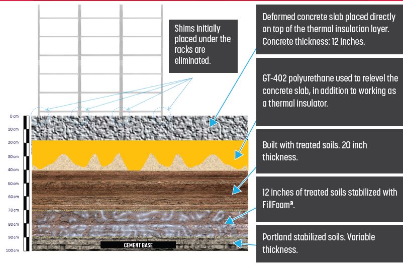
To reduce vertical forces to the ground and reduce the risk of structural damage, it was necessary to restore and increase the load bearing capacity of the soil by injecting water-insensitive, pre-expanded FillFoam® and HMI®402 polyurethane near the surface to properly re-level the concrete slabs. The injection of polyurethane is working as thermal insulation. HMI polyurethane injections were completed from midnight to 6 AM.
THE SUMMARY
Injection of high density FillFoam® and hydro-insensitive HMI®402 polyurethane was completed to re-level and increase insulation. This will reduce the clients electrical costs by 25% without disturbing operations.

• FillRite Technologies
✆ (866) FILLRITE
✆ (866) 345-5748
• info@fillritetech.com
FillRite Technologies © All Rights Reserved Ι Privacy Policy Ι Terms of Service